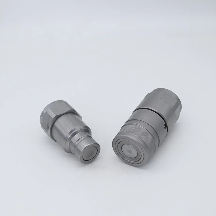
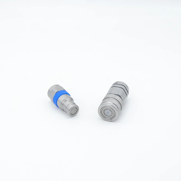
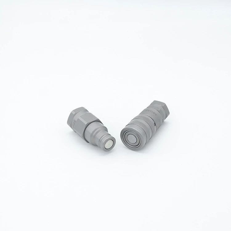
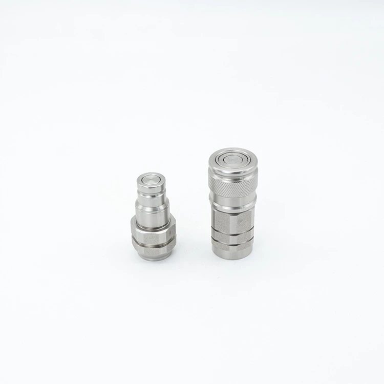
Zero-Defect Manufacturing: Advanced Quality Assurance and Testing Protocols for Hydraulic Quick Couplings and Valves
Zero-Defect Manufacturing: Advanced Quality Assurance and Testing Protocols for Hydraulic Quick Couplings and Valves
Published: August 7, 2026 Article Type: Production Process Keywords: hydraulic coupling quality control, ISO 16028 testing, burst pressure test, impulse fatigue testing, salt spray test, leak detection, SPC, Feiman quality assurance
Introduction
In our July 31 article, we walked through the complete production process of hydraulic quick couplings and valves — from raw material to finished product. This article zooms in on the most critical dimension of that process: quality assurance and testing.
A hydraulic quick coupling operating at 315 bar is a safety-critical component. A single defective seal, an undersized thread, or a hairline crack from improper heat treatment can cause catastrophic failure — equipment downtime, environmental contamination, even personal injury. Industry studies estimate that 58% of hydraulic system failures originate at connection points, with seal degradation (34%), loosening (16%), and mismatched installation (8%) as the leading causes.
For global exporters like Feiman Fluid Technology, quality is not an aspiration — it is a contractual obligation. This article details the multi-layered testing and quality assurance system that ensures every coupling and valve leaving the factory meets international standards and customer specifications.
1. The Quality Management Framework: ISO 9001:2000 in Practice
1.1 System Structure
Feiman operates under an ISO 9001:2000 certified quality management system (QMS) that governs every aspect of production. The system is structured around the Plan-Do-Check-Act (PDCA) cycle:
| QMS Element | Implementation at Feiman |
| Quality manual | Documents the overall quality policy, organizational structure, and process flow |
| Procedure documents | Step-by-step work instructions for machining, assembly, testing, and packaging |
| Quality plan | Product-specific inspection points, acceptance criteria, and test methods defined per order |
| Record control | All inspection records, test reports, and material certificates retained for minimum 5 years |
| Internal audit | Regular scheduled audits of all production and inspection processes |
| Management review | Quarterly quality reviews with corrective and preventive action (CAPA) tracking |
| Supplier quality | Approved Supplier List (ASL) with periodic performance evaluation |
1.2 Traceability: From Steel Mill to Shipping Dock
Every component carries full backward traceability:
- Raw material: Each bar or billet arrives with a mill certificate (EN 10204 Type 3.1) specifying chemical composition and mechanical properties
- Heat/lot number: Stamped or tagged on each blank, linked to the material certificate
- Process routing: A traveler document accompanies each batch through every operation — CNC station, heat treatment batch, surface treatment lot, assembly line
- Final marking: Finished couplings are laser-marked or stamped with model number, thread spec, batch code, and date code
- Test record: Pressure test data, dimensional inspection results, and salt spray test certificates are archived by batch
This traceability chain means that if a customer reports a field issue years later, Feiman can trace the component back to the exact material heat, machining setup, heat treatment batch, and operator.
2. Incoming Material Inspection: Quality Starts at the Dock
2.1 Material Verification Protocol
Raw materials are not released to production until they pass incoming inspection:
| Inspection Item | Method | Acceptance Criteria |
| Chemical composition | Spectrometer analysis (OES) | Conforms to material grade spec (e.g., 45# carbon steel per GB/T 699) |
| Mechanical properties | Tensile test, hardness test | Tensile strength, yield strength, elongation within spec range |
| Dimensional check | Caliper, micrometer | Bar diameter, straightness, length within tolerance |
| Visual inspection | Manual examination | No cracks, seams, decarburization, or surface defects |
| Material certificate | Document review | EN 10204 3.1 certificate matches physical material |
For stainless steel (304, 316L), additional corrosion resistance verification may be performed using intergranular corrosion testing per ASTM A262 for critical applications.
2.2 Seal and Component Supplier Quality
Seals (O-rings, backup rings, lip seals) are sourced from qualified suppliers with material certifications. Each seal batch is verified for:
- Material identification: FTIR (Fourier Transform Infrared) spectroscopy confirms elastomer type (NBR, FKM, EPDM, etc.)
- Hardness: Durometer measurement per ASTM D2240 (e.g., NBR 70±5 Shore A)
- Dimensional accuracy: Cross-section diameter and inner diameter within tolerance
- Batch consistency: Compression set testing on sample basis
Springs are inspected for free length, spring rate, and load at deflection, ensuring consistent valve actuation force across production batches.
3. In-Process Quality Control: Catching Defects Before They Propagate
3.1 Statistical Process Control (SPC)
Key machining dimensions are monitored using SPC charts to detect process drift before it produces nonconforming parts:
| Control Parameter | Measurement Tool | SPC Chart Type | Typical Tolerance |
| Sealing diameter | Precision micrometer | X̄-R chart | ±0.01 mm |
| Valve seat angle | Optical comparator | X̄-R chart | ±0.5° |
| Thread pitch diameter | Thread micrometer / ring gauge | Go/No-Go + variables | 6g or 4H class |
| Surface roughness (Ra) | Profilometer | X̄-R chart | Ra ≤ 0.8 µm (sealing surfaces) |
| Concentricity | CMM | X̄-R chart | ≤ 0.02 mm |
When SPC data indicates a trend toward the control limit, the process is adjusted before parts fall outside specification — preventing scrap and ensuring consistent quality.
3.2 First Article Inspection (FAI)
For every new product, production lot, or setup change, a First Article Inspection is performed:
- Full dimensional verification of all critical features
- CMM (Coordinate Measuring Machine) report covering 100% of drawing dimensions
- Thread verification with GO/NO-GO gauges
- Surface finish measurement on all sealing surfaces
- Hardness verification on heat-treated features
The FAI report is reviewed and approved by the quality engineer before production continues.
3.3 In-Process Inspection Frequency
| Production Stage | Inspection Method | Frequency |
| CNC turning | Operator self-check + IPQC patrol | Every 10–20 pieces (operator); every 50 pieces (IPQC) |
| Thread cutting | GO/NO-GO gauge | 100% critical threads; sampling for non-critical |
| Heat treatment | Hardness test (Rockwell) | 3–5 samples per batch |
| Surface treatment | Thickness measurement + visual | 5 samples per rack/batch |
| Assembly | Function check (connect/disconnect) | 100% |
4. Pressure Testing: The Non-Negotiable Gate
4.1 100% Pressure Test Policy
Every single coupling produced at Feiman undergoes pressure testing before shipment — no exceptions, no sampling. This is the cornerstone of the quality assurance system.
4.2 Test Protocol
The pressure testing protocol follows a multi-stage approach aligned with ISO 16028 and ISO 7241 requirements:
| Test Stage | Pressure Level | Duration | Acceptance Criteria |
| Low-pressure leak check | 0.5–1.0 MPa (5–10 bar) | 5 seconds | No visible leakage (air-under-water or pressure decay) |
| Working pressure test | Rated working pressure (e.g., 21/31.5 MPa) | 30–60 seconds | No leakage, no permanent deformation |
| Proof pressure test | 1.5× rated working pressure | 30 seconds | No leakage, no visible deformation |
| Burst test (sampling) | Minimum 3× rated working pressure | To failure | Burst pressure ≥ 3× working pressure per ISO 16028 |
For example, an ISO 16028 DN12.5 (1/2") flat-face coupling rated at 25 MPa (250 bar) must withstand:
- Proof pressure: 37.5 MPa (375 bar) without leakage
- Burst pressure: minimum 75 MPa (750 bar) before rupture
4.3 Test Equipment and Methods
Hydrostatic pressure test bench: Couplings are connected to a test fixture and pressurized with hydraulic oil. Pressure is monitored by calibrated digital transducers (accuracy ±0.25% full scale). The test bench automatically records peak pressure, hold time, and any pressure drop indicating leakage.
Pneumatic leak test (air-under-water): For rapid in-line leak detection, couplings are pressurized with compressed air and submerged in a water bath. Any bubble formation indicates a leak path. This method is fast, clean, and suitable for 100% production testing.
Pressure decay test: For applications requiring higher sensitivity, the coupling is pressurized and isolated. The system monitors pressure decay over a defined time period. A decay rate exceeding the threshold indicates micro-leakage. This method can detect leaks as small as 10⁻³ sccs (standard cubic centimeters per second).
Helium mass spectrometry (optional): For ultra-high-purity applications (semiconductor, hydrogen, pharmaceutical), helium leak testing provides detection sensitivity down to 10⁻⁹ sccs — approximately 1,000 times more sensitive than pressure decay.
5. Endurance and Fatigue Testing: Validating Long-Term Reliability
5.1 Impulse Pressure Testing (ISO 6803)
The most demanding endurance test for hydraulic couplings is impulse pressure cycling per ISO 6803. The test subjects the coupling to rapid pressure cycles simulating real-world hydraulic system pulsations.
ISO 16028:2023 updated requirements (superseding the 1999 edition):
| Test Condition | Requirement |
| Coupled state impulse cycles | 1,000,000 cycles (increased from 200,000 in the 1999 edition) |
| Uncoupled state impulse cycles | 100,000 cycles |
| Pressure waveform | Half-sine or sawtooth, 0 to 1.33× rated pressure |
| Cycle frequency | 30–75 cycles/minute |
| Test fluid temperature | 40 ± 5°C (standard); elevated temperature variants for specific applications |
| Acceptance criteria | No leakage, no component failure, no visible cracks |
This test confirms that the coupling can survive years of hydraulic system pressure pulsation without seal degradation or structural fatigue.
5.2 Connect/Disconnect Cycle Life Testing
Beyond pressure impulse testing, couplings are tested for mechanical connection cycle durability:
| Test Parameter | Typical Requirement |
| Cycle count | 5,000–100,000 connect/disconnect cycles (application-dependent) |
| Test pressure | Rated working pressure during connection |
| Acceptance criteria | No leakage after cycling; seal performance degradation ≤ 15% |
| Additional checks | Locking mechanism retention force, sleeve operation torque, visual wear assessment |
For construction machinery applications where couplings may be connected and disconnected daily, this test validates that the locking balls, sleeve, and valve mechanism will maintain reliable operation throughout the product's service life.
5.3 Burst Pressure Verification
Burst testing to destruction is performed on a sampling basis to verify the safety margin:
| Coupling Type | Rated Pressure | Minimum Burst Pressure | Safety Factor |
| ISO 16028 DN6.3 | 31.5 MPa (315 bar) | 126 MPa (1,260 bar) | 4:1 |
| ISO 16028 DN12.5 | 25 MPa (250 bar) | 125 MPa (1,250 bar) | 5:1 |
| ISO 16028 DN51 | 10 MPa (100 bar) | 40 MPa (400 bar) | 4:1 |
| ISO 7241 Series A DN12.5 | 21 MPa (210 bar) | 84 MPa (840 bar) | 4:1 |
Burst testing confirms that the coupling's structural design provides adequate safety margin above maximum rated pressure, protecting users from catastrophic failure under overload conditions.
6. Environmental and Corrosion Testing
6.1 Salt Spray Testing (ASTM B117 / ISO 9227)
Surface treatment effectiveness is validated through neutral salt spray (NSS) testing:
| Surface Treatment | Test Duration | Acceptance Criteria |
| Zinc plating (Zn) | 96–240 hours | No red rust (base metal corrosion) |
| Zinc-nickel (Zn-Ni) | 500–1,000 hours | No red rust; ≤ 5% white rust |
| Chrome plating | 240–500 hours | No red rust |
| Stainless steel (passivated) | 500–1,000+ hours | No pitting or staining |
| Electrophoretic coating (E-coat) | 500–1,000 hours | No red rust |
Salt spray duration requirements are specified based on the target export market and application environment. Marine, offshore, and mining applications typically demand 500+ hours of salt spray resistance.
6.2 Temperature Cycling and Thermal Shock
Couplings destined for extreme climate applications undergo thermal cycling:
- Cold soak: -40°C for 4 hours
- Hot soak: +120°C for 4 hours
- Transition: Rapid transfer between chambers
- Cycles: Minimum 5 complete thermal cycles
- Acceptance: No seal extrusion, no cracking, no leakage at rated pressure post-cycling
6.3 Vibration Testing
For mobile equipment applications, couplings may be subjected to vibration testing per ISO 16750-3 or customer-specific standards:
- Frequency range: 10–500 Hz
- Acceleration: 2–5 g
- Duration: 8–24 hours per axis
- Acceptance: No loosening of threaded connections, no leakage, no component fatigue
7. Hydraulic Valve-Specific Testing
Hydraulic valves require additional testing beyond coupling protocols due to their flow control function:
| Test | Purpose | Method |
| Cracking pressure test | Verify valve opens at specified pressure | Gradually increase upstream pressure; record opening point |
| Flow capacity test | Confirm rated flow at specified pressure drop | Calibrated flow loop with pressure transducers |
| Internal leakage test | Measure leakage across closed valve | Pressurize inlet; measure outlet drip rate (≤ specified mL/min) |
| Re-seat pressure test | Verify valve closes fully after operation | Cycle valve; measure re-seal pressure and leakage |
| Response time test | Measure valve actuation speed | High-speed pressure transducer; typically ≤ 50 ms for solenoid valves |
| Manual override test | Confirm manual operation functions | Physical actuation; verify full open/close travel |
For ball valves, seat tightness is verified using bubble-tight shutoff testing per API 598 or FCI 70-2 (Class VI shutoff: no visible leakage at rated differential pressure).
8. Failure Analysis and Continuous Improvement
8.1 Nonconformance Management
When a part fails any inspection or test, the following process is triggered:
- Quarantine: Nonconforming part is isolated and tagged to prevent shipment
- Investigation: Quality engineer performs root cause analysis (RCA) using 5-Whys, fishbone diagram, or FMEA
- Disposition: Part is reworked, re-inspected, or scrapped based on engineering review
- Corrective action: Process adjustment or tooling change implemented to prevent recurrence
- Verification: Next production batch monitored to confirm corrective action effectiveness
- Documentation: Full CAPA (Corrective and Preventive Action) record filed and reviewed
8.2 Key Quality Metrics Tracked
| Metric | Target | Current Performance |
| First-pass yield | ≥ 98% | Monitored daily by product line |
| Customer return rate | < 100 ppm | Tracked monthly |
| On-time delivery | ≥ 95% | Tracked per order |
| Internal audit findings | Zero critical | Quarterly audits |
| Field failure rate | < 50 ppm | Tracked annually by product family |
9. Certification and Documentation for Export Markets
9.1 Standard Documentation Package
Every shipment from Feiman includes a documentation package tailored to export requirements:
| Document | Content | Purpose |
| Material certificate | EN 10204 3.1 per heat/lot | Material traceability |
| Pressure test report | 100% tested, with batch data | Proof of pressure integrity |
| Dimensional inspection report | Key dimensions + CMM data | Conformance verification |
| Salt spray test certificate | Duration and result | Corrosion resistance validation |
| Certificate of Conformity (CoC) | Product meets specified standards | Customer/regulatory compliance |
| Packing list | Part numbers, quantities, batch codes | Logistics and receiving |
| Country of origin certificate | Made in China | Customs clearance |
9.2 Market-Specific Compliance
| Export Market | Key Compliance Requirements |
| European Union | CE marking (where applicable), REACH compliance for materials, RoHS for coatings |
| United States | ABS/DNV type approval (for marine), ASME B31.3 compliance (for process piping) |
| Australia | WaterMark certification (for water applications), AS/NZS standards |
| Oil & gas | API Spec 6A / API Spec Q1, NACE MR0175 for sour service |
| Mining | Flameproof certification (for underground), IECEx |
10. Feiman's Quality Assurance Infrastructure
10.1 Inspection and Test Equipment
| Equipment | Function | Calibration |
| Hydrostatic pressure test bench (multiple units) | 100% pressure testing up to 100 MPa | Calibrated annually per ISO 17025 |
| CMM (Coordinate Measuring Machine) | High-precision dimensional verification | Annual calibration + daily artifact check |
| Surface roughness tester | Ra/Rz measurement on sealing surfaces | Annual calibration |
| Rockwell / Vickers hardness tester | Heat treatment verification | Daily verification with reference blocks |
| Salt spray test chamber | Corrosion resistance testing | Per ASTM B117 / ISO 9227 |
| Thread gauges (GO/NO-GO) | Thread dimensional verification | Calibrated per ISO 1502 |
| Spectrometer (OES) | Material chemical composition | Certified reference samples |
| Durometer | Seal hardness verification | Daily verification |
| Air-under-water test tank | Pneumatic leak detection | Visual observation standard |
| Impulse test rig | Fatigue life testing per ISO 6803 | Annual calibration |
10.2 Personnel and Training
- All inspection personnel hold relevant qualifications and receive annual retraining
- Welding inspectors (where applicable) are certified to CWI or equivalent
- Pressure test operators are trained in safety protocols for high-pressure testing
- Quality engineers maintain familiarity with evolving international standards
Conclusion: Quality Is a System, Not a Slogan
The difference between a coupling that lasts 10,000 cycles and one that fails at 500 is not luck — it is the cumulative result of hundreds of controlled decisions: material specification, machining tolerance, heat treatment parameters, surface treatment thickness, seal compression, and above all, rigorous testing at every stage.
At Feiman Fluid Technology, the quality assurance system is built on three non-negotiable principles:
- 100% pressure testing — no coupling ships without passing
- Full traceability — every part traceable from steel mill to shipping container
- Continuous improvement — every failure investigated, every process refined
For OEM buyers, distributors, and end-users who depend on hydraulic system reliability, understanding a supplier's quality protocols is not due diligence — it is risk management. We invite customers to audit our facilities, review our test procedures, and verify that the couplings and valves bearing the Feiman name are built to perform.
For quality documentation requests, factory audit scheduling, or technical consultations, please contact the Feiman quality assurance team.
About Feiman Fluid Technology
Hebei Feiman Machinery Parts Co., Ltd. was established in 2014 and is located in the Rubber and Plastic Pipe Industry Base, Jingxian, Hengshui, Hebei Province, China. It is a professional manufacturer focused on hydraulic and fluid power system solutions. The company's product portfolio includes quick release couplings, hydraulic valves, hydraulic connectors, pipe clamps, and pressure test equipment, serving construction machinery, petrochemicals, metallurgy and mining, agricultural machinery, marine engineering, and new energy equipment industries globally.
Contact:
- Tel: +86 15369362101
- Website: www.feimanfluid.com
Copyright belongs to Hebei Feiman Machinery Parts Co., Ltd. Please indicate the source when reproducing.